USB Audio DAC

Before I begin, I'd like to shout out Phil's Lab on YouTube, his videos were instrumental in learning how to design PCBs for microcontrollers.
I recently finished my first semi-successful foray into the world of electrical engineering. Hardware design has been a long-time hobby of mine, but also a skill where my expectations are far greater than my actual knowledge.
Because of this, past projects never really went to plan. Many years ago I decided to make an oscillator module for a modular synthesizer. Though this past attempt failed, I continued pursuing a music-related design. In this case, I was having trouble with the audio interface for my computer. A good audio interface should provide low latency, high fidelity audio to your headphones or speakers with a simple USB connection to the computer.
To start my design I booted up KiCAD. In the past, I had worked with EasyEDA simply because the integration with JLCPCB was convenient. This time, however, I needed to buy some specialized components that weren't available through LCSC. Furthermore, in my tests with KiCAD, it seemed to simply perform better than EasyEDA in every way.
To start off, I needed to pick a DAC, which will convert the digital signal from the computer (and in turn the microcontroller) to analog audio signals. For this, I decided to pick a relatively affordable DAC from ESS as I know the DACs they make sound good, and are easy to hook up. I ended up picking the ES9023P
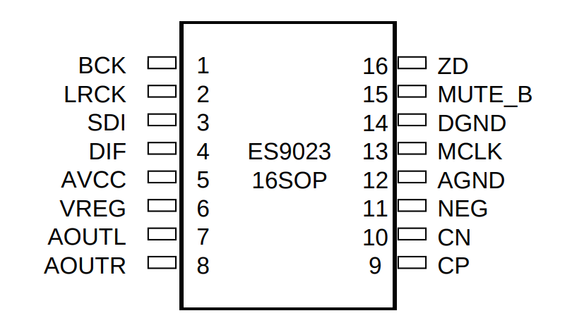
It has a stereo output, an I2S (or left justified PCM) input, and minimal other external requirements.
Next, I needed a microcontroller, which would interface with the computer, process USB audio packets, and send them off to the DAC via the I2S interface. I picked the STM32G473CCU6, it was probably overkill for this application but Mouser had plenty of stock and the price difference was negligible.
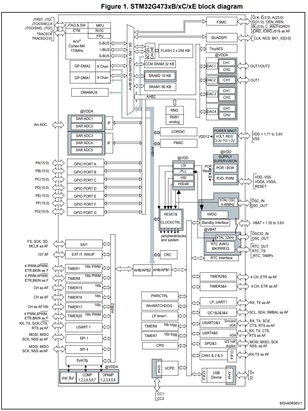
It has plenty of I/O and a ton of analog circuitry that I didn't make use of. It has a relatively high clock speed at 170Mhz which is ideal for audio processing.
Once the schematic had been completed it was time to construct the board layout. this caused a lot of frustration, and I ended up cutting the bottom ground layer more than I would have liked.
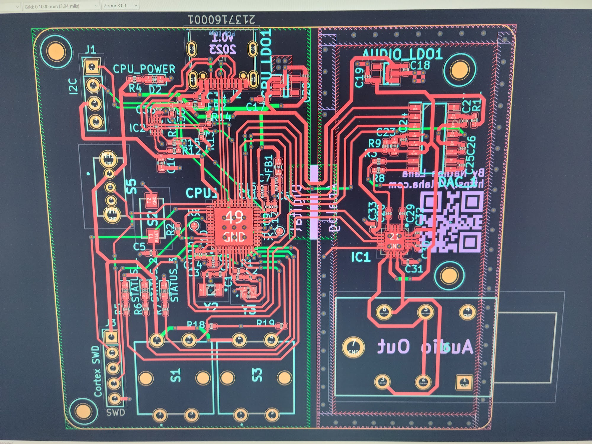
I split the ground plane into two sections and connected them with a central bridge. I don't know if this actually helped to reduce noise but it certainly looked cool.
After double-checking everything I ordered the PCBs, a solder paste stencil, and the components from OSHPark, Mouser, and OSHStencils.
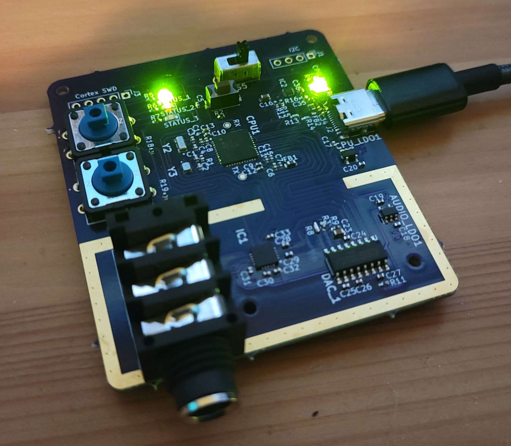
And after a week or so of waiting, my beautiful purple PCBs arrived!
The next step was soldering. Up until now, I had only ever done traditional through-hole soldering with an iron, this time however, I needed to solder components less than a millimeter wide. Though this would normally be done in a special temperature-controlled reflow oven, all I had available was a hot air rework station. I was nervous to say the least.
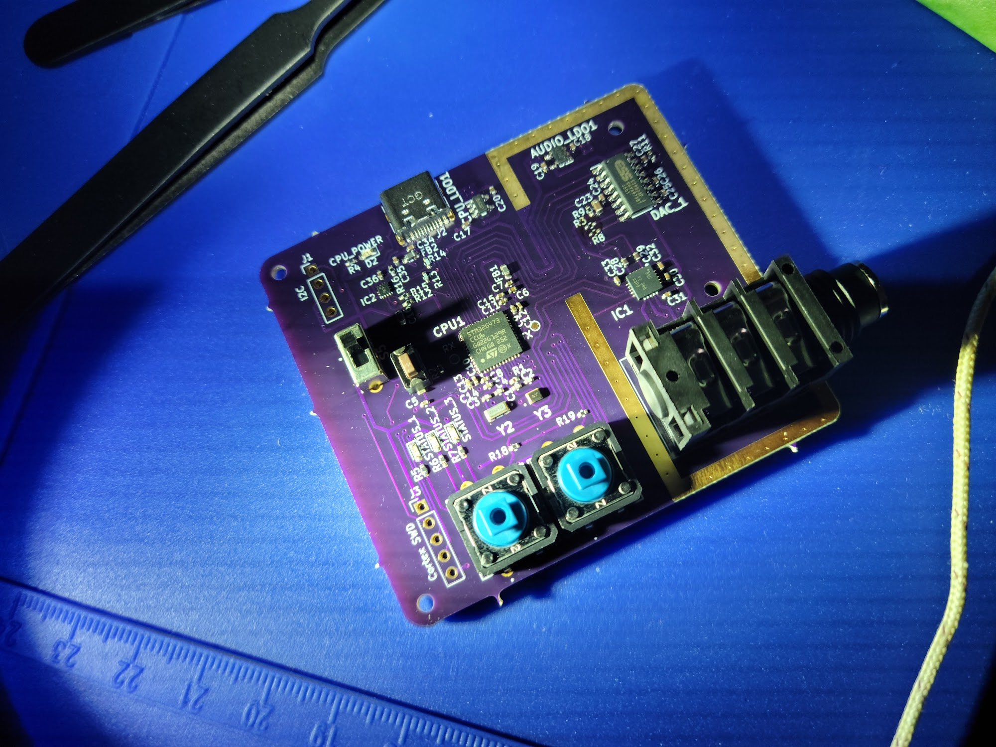
Surprisingly, this process went quite well and everything just slid into place when the heat was applied. And even better, after applying power to the USB port, there was no magic smoke!
However, this wasn't the end of the journey, after tearing off the USB-C port and somehow soldering it back on, I still had a ton of programming ahead of me. This is when I noticed something terrible...
My previous experience with microcontrollers had been with development boards. These boards are ready-to-go and contain helpful pin headers used to connect to a breadboard without soldering. Traditionally, when connecting I2C devices to these development boards I would simply hook up power, ground, SDA, and SCL. However, on the PCB I had neglected to realize the STM32 cannot power the SDA and SCL lines without a pull-up resistor that brings those lines up to logic high (3.3v). This was a problem as I could no longer talk to the headphone amplifier and thus was stuck in a software shutdown and mute state.
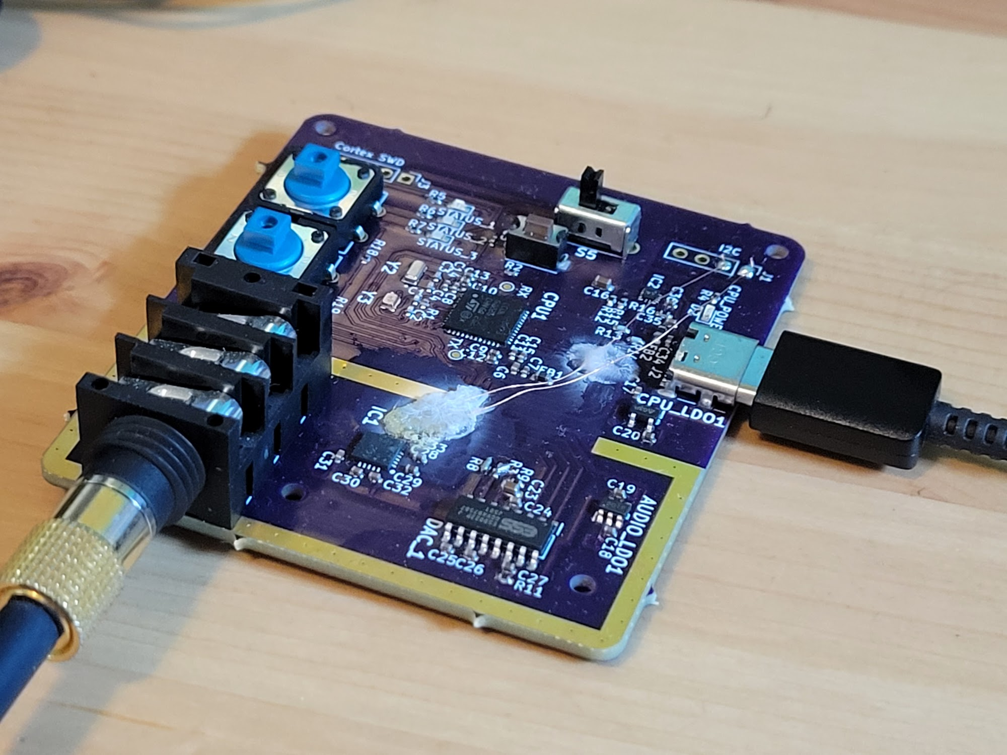
After a few days of procrastination, I finally picked up the board and attempted a fix. After all, what was there to lose? My plan was this:
- Scrape off the solder mask from the traces going to the headphone amplifier
- Use magnet wire to connect the auxiliary I2C interface I had reserved for other peripherals to said traces
- ???
- Profit?
And with enough super-glue, the end result wasn't pretty but it worked! I was able to communicate with the amplifier and had output from the 1/4-inch audio jack.
The audio produced is mostly good, though at a resolution of 16-bit, it won't be winning any awards for quality. I also encountered an intermittent audio glitch (digital noise sound) that has yet to be resolved.
With that, my project was complete, and though it's a pretty terrible audio interface, it was an incredible learning experience.